Since its release, the adoption of Cisco’s ACI and its APIC controller have continuously gained rapid traction in the market. Clients loved the network giant’s take on SDN so much so that their demands almost immediately changed years into its existence.
It didn’t take Cisco long before it followed up a Cisco APIC release for its 1.2.1i that comes with a new streamlined way of connecting service devices — the unmanaged mode. Steering away from the traditional two methods of connecting devices,
Today, Lumos will give you a walkthrough on L4-L7’s Unmanaged Mode alongside a few useful guides on verifying contracts on the said design.
L4-7 Unmanaged Go-Through Mode (Transparent FW)
Our team has been experimenting around service graphs for quite some time and have decided to share our findings with the aforementioned deployment. The said deployment of service graphs uses the ACI fabric (2.2(1n), an ASAv as well as an CSR Router.
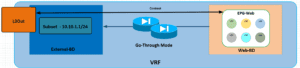
The featured design is an unmanaged transparent mode deployment with routing provided by the ACI fabric scale. Our team used two bridge domains alongside a default gateway for the servers with the IP address of the subnet in the external domain bridge.
The table above showcases the required setting of each bridge domain in order for the configuration to work properly.
| Feature | External BD | Web BD |
| Hardware Proxy | No | No |
| ARP Flooding | Yes | Yes |
| Unicast Routing | Yes | No |
| Subnet | Yes | No |
| Subnet Check | Yes | No |
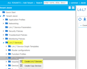
After our VRF, Bridge Domain and EPG’s are created, our team went ahead to create a L4-7 service.
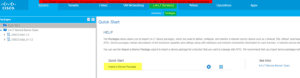
Once the Cisco-ASA-1.2 Package was installed, they went to “Create an L4-L7 Device” with our tenant.
Uncheck the “Managed” tick box and fill in the parameters below:
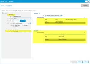
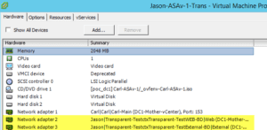
Note: Device interfaces are the network adapters in vCenter and the Cluster interfaces are the concrete interfaces of the ASAv.
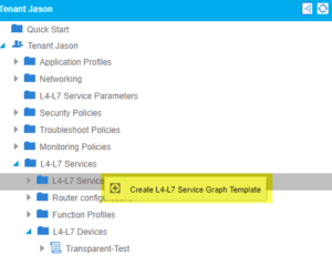
Our team was then required to build a service graph template:
We want to drag the L4-L7 device we just created between our two EPG’s and name everything accordingly:
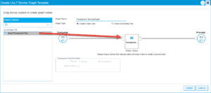
After completion of the service graph template we need to apply this template for it to take effect (we can also reuse this template in the future if necessary):
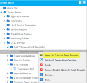
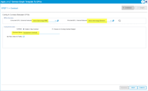
Applying this service graph requires us to select our EPG’s we are associating this with as well as creating a bogus contract that we can allow all traffic through:
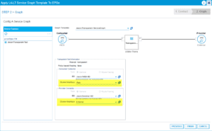
Finish the process by stating what cluster/concrete interfaces we will be using:
Our team then counted the contracts that were created and applied correctly:
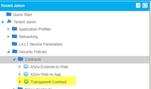
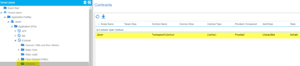
While it seems like it’s only an external EPG, our team made sure that Web was applied correctly as well.
Afterwards, our team verified the port-groups created earlier in vCenter and assigned each one to its correct interfaces:
Once the service graph looked sufficient, our team still had to configure an FW since the design will be deployed in the unmanaged mode. Here’s a basic FW config and parse text that features the transparent parameters, bvi etc.:
:
ASA Version 9.4(4)
!
firewall transparent
hostname Jason-ASAv-Transparent!
!
interface GigabitEthernet0/0
nameif web
bridge-group 1
security-level 100
!
interface GigabitEthernet0/1
nameif external
bridge-group 1
security-level 0
!
interface Management0/0
management-only
nameif management
security-level 0
ip address x.x.x.x/24
!
interface BVI1
ip address 10.10.1.2 255.255.255.0
same-security-traffic permit inter-interface
access-list web-in extended permit ip any any
access-list external-in extended permit ip any any
logging enable
logging buffer-size 524288
logging console emergencies
logging monitor debugging
logging buffered debugging
logging trap notifications
logging asdm informational
mtu web 1500
mtu external 1500
mtu management 1500
no failover
no monitor-interface service-module
icmp unreachable rate-limit 1 burst-size 1
icmp permit any web
icmp permit any external
access-group web-in in interface web
access-group external-in in interface external
ssh 0.0.0.0 0.0.0.0 management
ssh timeout 5
ssh version 2
After configuring the FW, our team tested the communication from a VM that lives behind the FW to our gateway that lives in the External-BD:
Host:

Web EPG:
![]()
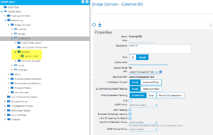
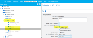
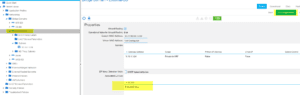
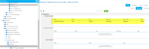
BD External:
Subnet 10.10.1.1/24
Observe how the settings on the right side of the BD. It is crucial you are flooding for communication to take place. Settings are listed in the table at the top of the post.
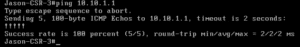
Communication test:
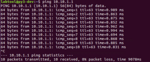
Perfect!! We can reach the External BD Gateway through the FW. Let’s also check the FW and see if we are seeing the same thing:
Show log:
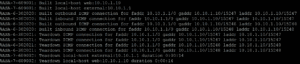
The FW is now verifying the same communication.
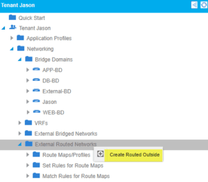
Going back to the previous discussion earlier, our design had an L3Out attached to the fabric so we can reach external hosts. We can now start building the L3Out. Note that one is required to have previous understanding of L3Out in order to do this process.
For this L3Out, we will be using a CSR router and not using just a simple VMM Domain connectivity to the fabric passing vlans. We went back to our tenant and right-click on external routed networks:
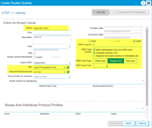
Assuming you have experience with L3Outs configure the initial parameters, we will now be using OSPF in Area 0 for this example:
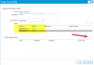
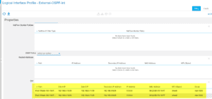
Create our Node Profile for each feature, OSPF Int Profile and Network EPG:
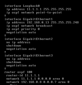
Once that is completed ,we need a simple config on our CSR:
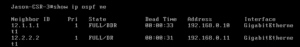
Remind yourself to check for neighbors:
ACI:
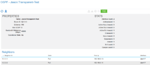
CSR:
Once we have neighbors, we can start doing routes.
ACI:
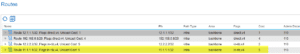
We now see the loopback from the CSR in our routing table.
CSR:
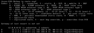
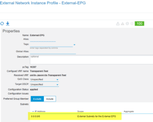
While we are getting loopbacks from ACI, we are supposed to be receiving the 10.10.1.0/24 within the External-BD. These issues usually live inside the bridge domain settings. So once you see them, investigate:
Our subnet is still set to private, hence we need to advertise externally and select the correct L3Out:
L3Out within BD:
With these changes, ACI verifies routing on the CSR. Should you need a refresher on this step, feel free to check out the verified scalability guide for Cisco ACI.
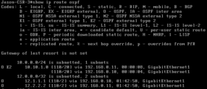
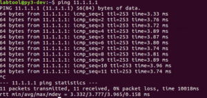
Now we can now see the 10.10.1.0/24 subnet on the external router. Our host can now ping the loopback of the router:
If we still can’t hit the loopback of the router, look back at our design again. Notice how we still need a contract between the L3Out and the EPG, just like any other EPG to EPG communication.
Going back to earlier, we created and applied the service-graph template. Contracts were then created and applied on the Web EPG:
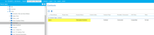
We must use this same contract on the L3Out Network EPG. If we apply correctly we should see communication take place:
We can now verify ACI:
Web Host:
Now we can test CSR:
There you have it! A working unmanaged service graph within ACI. Keep in mind that this is a simple implementation of the service graph. In a real-life situation, you would have very granular rules within your FW.
These implementations can vary in many ways. You could also include a one-arm load-balancer in this model with an additional bridge domain and more.
@_JBANK